All Tariffs & import fees are prepaid for shipments to the USA. The price you see is what you pay, delivered.
All Tariffs & import fees are prepaid for shipments to the USA.
Free Trackable Shipping to the USA
All Tariffs & import fees are prepaid for shipments to the USA.
Free Trackable Shipping to the USA
We had a choice. Raise prices for everyone, or reduce them for non-US countries.
Your country won with prices lowered by 15%. Click to learn more.
We had a choice. Raise prices for everyone, or reduce them for non-US countries.
Your country won with prices lowered by 15%. Click to learn more.
We had a choice. Raise prices for everyone, or reduce them for non-US countries. Your country won with prices lowered by 15%. Touch to learn more.
Low cost international shipping options now available!
Fast Tracks Document LibRary
FREE TO DOWNLOAD, FULLY ILLISTRATED BUILDERS GUIDES FOR ALL OF OUR TOOLS
All of our documents are in PDF format. You will need a PDF viewer to read and print them after downloading.
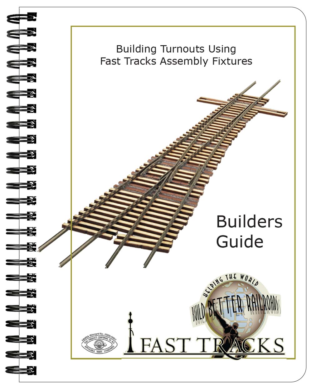
Building Turnouts Using Fast Tracks Assembly Fixtures
This fully illustrated document provides complete details for building switches using Fast Tracks tools & supplies. These instructions apply to Turnouts, Wyes & Curved Turnouts in all scales and include essential information for building any fixture-built trackwork.
Download Now
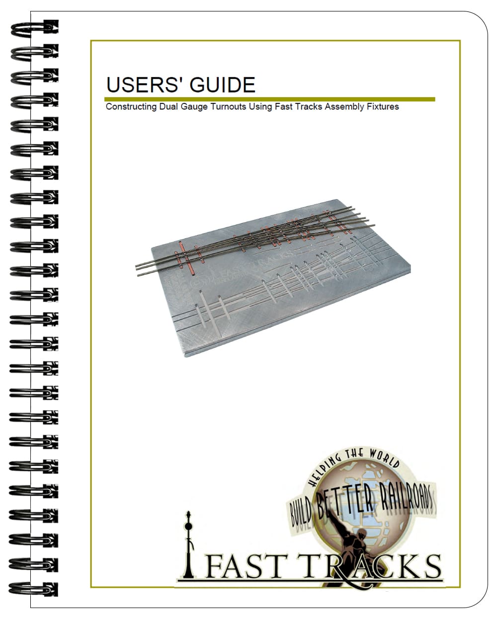
Building Dual Gauge Turnouts Using Fast Tracks Assembly Fixtures
This document provides details for building dual gauge turnouts using Fast Tracks tools & supplies. These instructions apply to Dual Gauge Turnouts in all scales.
Download Now
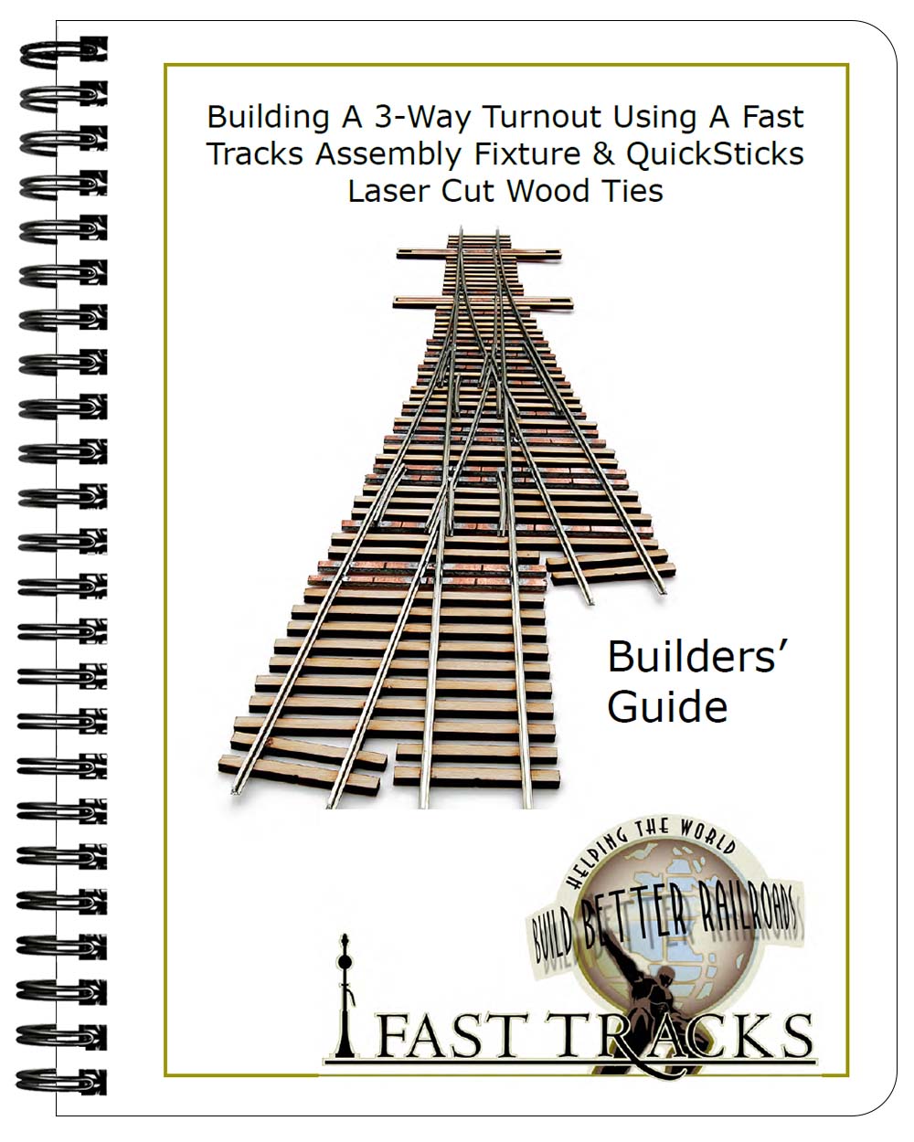
Building A 3-Way Switch With A Fast Tracks Assembly Fixture
This Builders Guide applies to three-way lapped turnouts in all scales and gauges.
Download Now
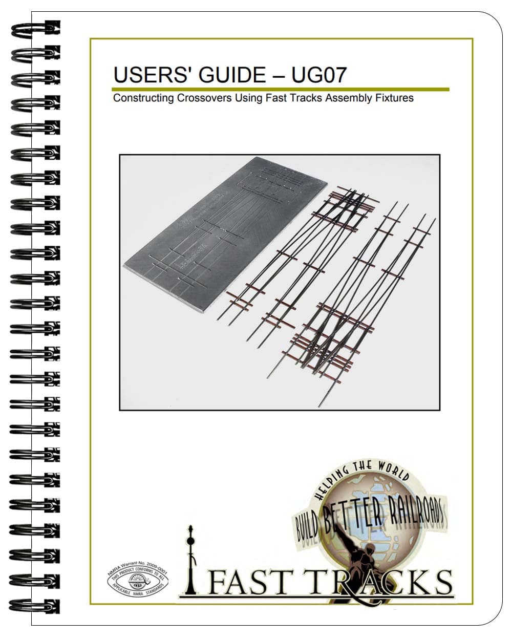
Building Double Crossovers With a Fast Tracks Assembly Fixture
These instructions apply to all scales and sizes of Crossovers.
Download Now
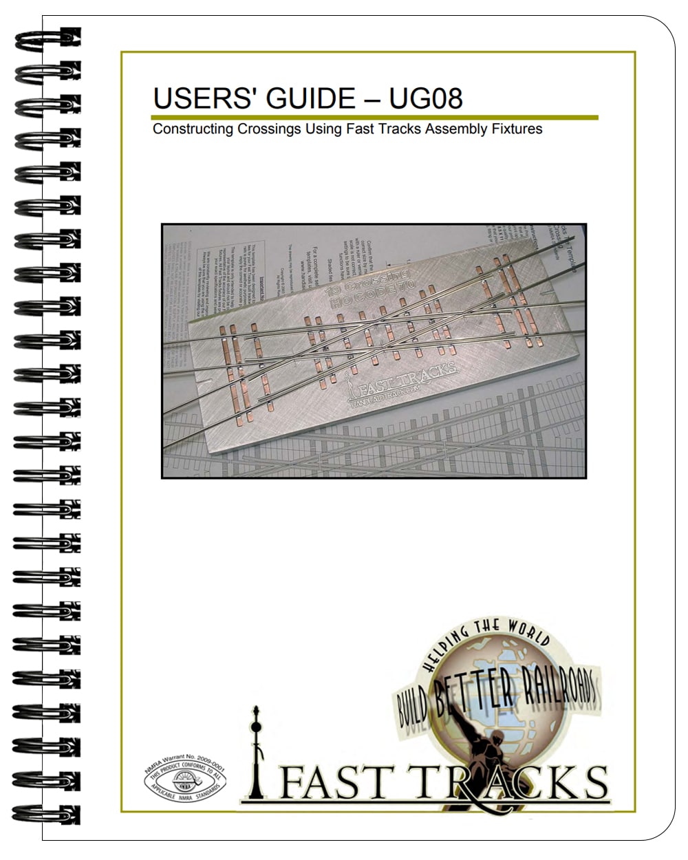
Building Crossings With A Fast Tracks Assembly Fixture
These instructions apply to all scales and sizes of fixture built crossings.
Download Now
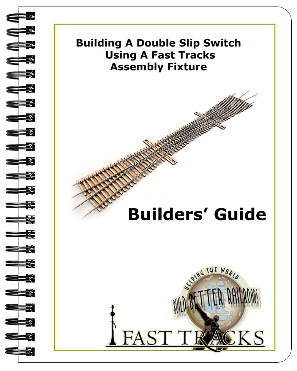
Building A Double Slip Switch With A Fast Tracks Assembly Fixture
These instructions apply to all scales and sizes of fixed frog Double Slips Switches.
Download Now
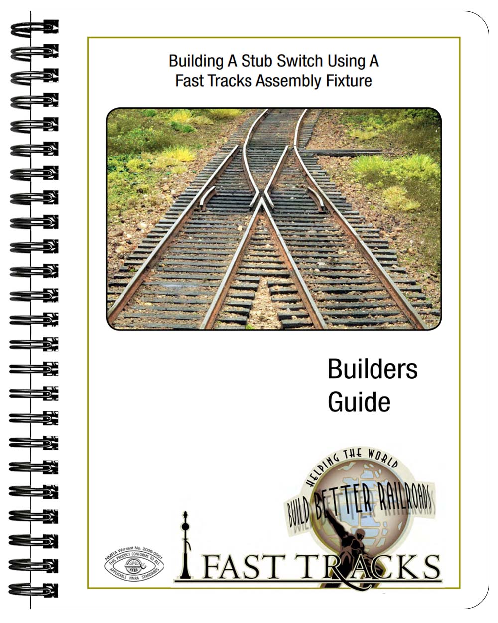
Building A Stub Switch Using A Fast Tracks Assembly Fixture.
Do you already own a Fast Tracks Assembly Fixture? Then you can use the same fixture and tools you have now to build a stub turnout with QuickSticks and PC Board ties.
Download Now
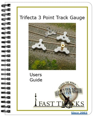
TRIFECTA 3 POINT TRACK GAUGE
Users Guide
Download Now
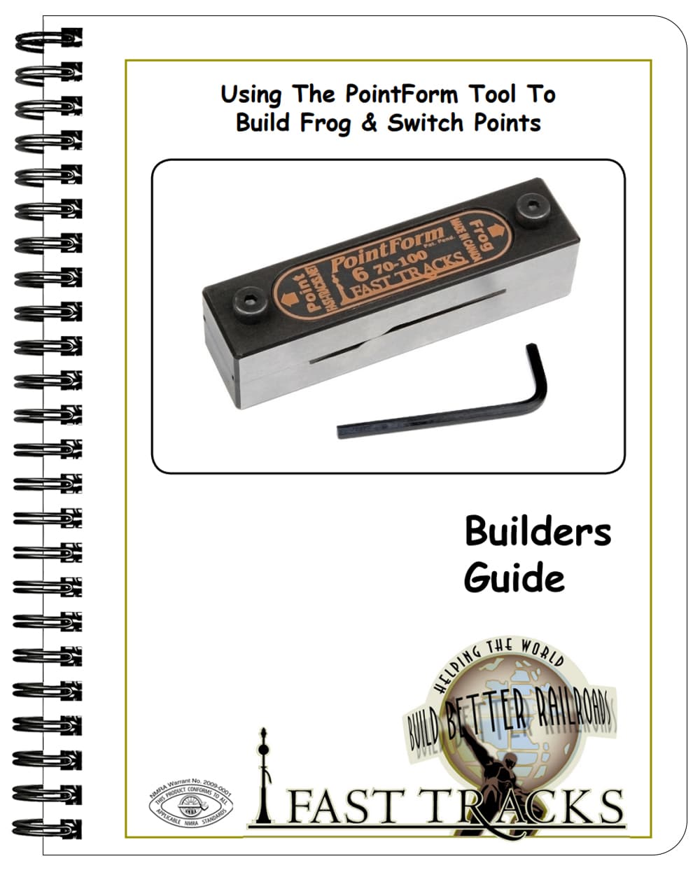
Using The PointForm Tool To Build Frog & Switch Points
We offer a number of different types of PointForm tools. This document provides general instructions on how to use a PointForm tool. These instructions apply to all PointForm tools.
Download Now
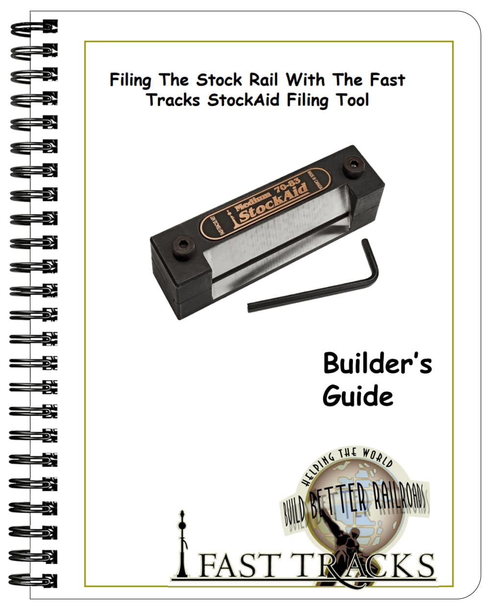
Filing The Stock Rail With The Fast Tracks StockAid Filing Tool
Using the StockAid tool to remove the base of the stock rail in a turnout. These instructions apply to all sizes of StockAid tools.
Download Now
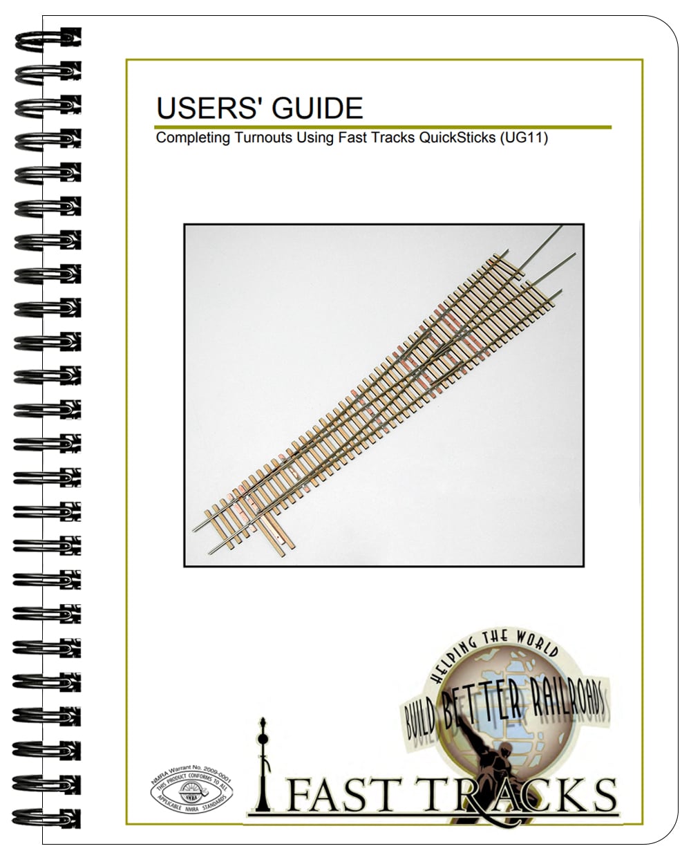
Completing Turnouts Using Fast Tracks QuickSticks
This Builders Guide details how to complete building your switch using QuickSticks laser-cut wood ties.
Download Now
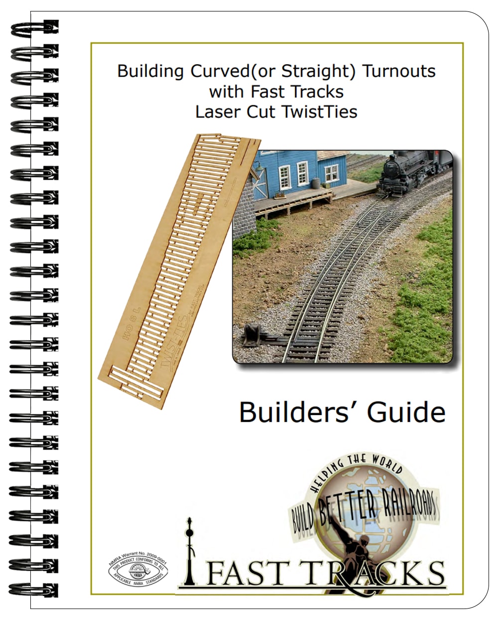
Building Curved (and Straight) Turnouts With Fast Tracks TwistTies
TwistTies offer an alternative to building switches using an assembly fixture, PC Board ties, and solder. Instead, the switch is built using a pre-cut all wood tie lattice. This document provides detailed instructions.
Download Now
Using the Frog Helper To Build Curved or Straight Turnout Frog Points
The Frog Helper tool works in the same manner as a full-sized assembly fixture but is specifically designed for building frog points. These instructions explain how to use the tool to construct curved or straight points and apply to all scales.
Download Now
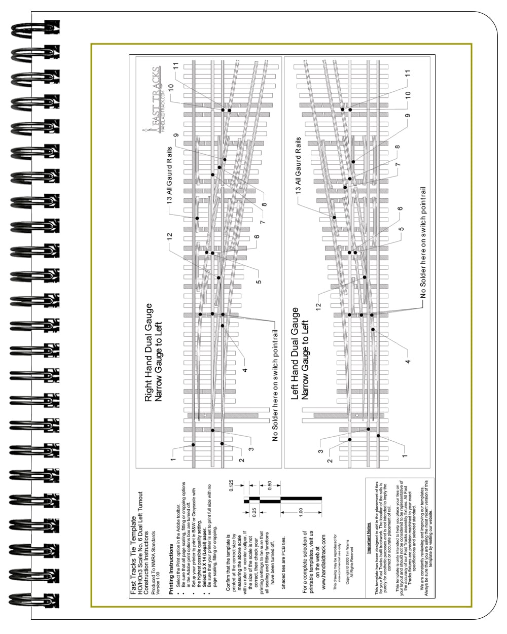
Building Template For Dual Gauge Left Side Turnouts
Use this template for guidance on the rail placing order in a Dual Gauge fixture. This applies to Dual Guage Left switches. (Left hand running)
Download Now
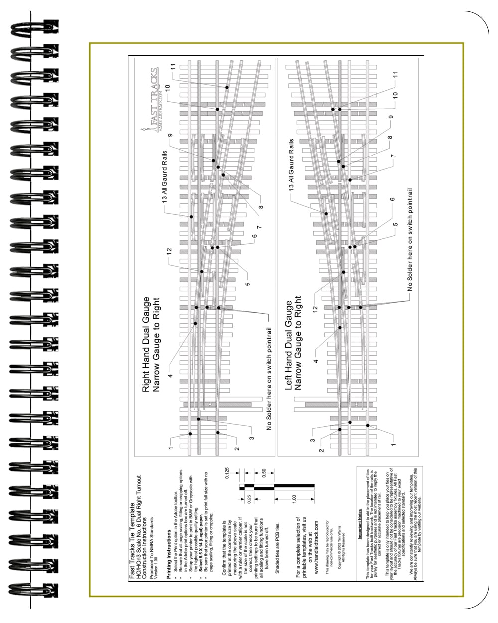
Building Template For Dual Gauge Right Side Turnouts
Use this template for guidance on the rail placing order in a Dual Gauge fixture. This applies to Dual Guage Right switches. (Right hand running)
Download Now
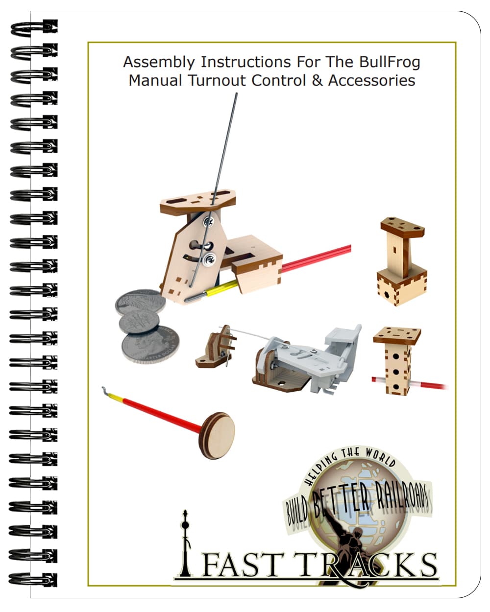
The BullFrog Switch Machine and Accessories
This all-in-one document provides complete instructions for assembling the BullFrog Manual Turnout Control, TadPole Remote Control Rod Mount, Control Rod Hanger/Joiner, Control Rod Kit, The SideWinder, and Decorative Knobs.
Download Now
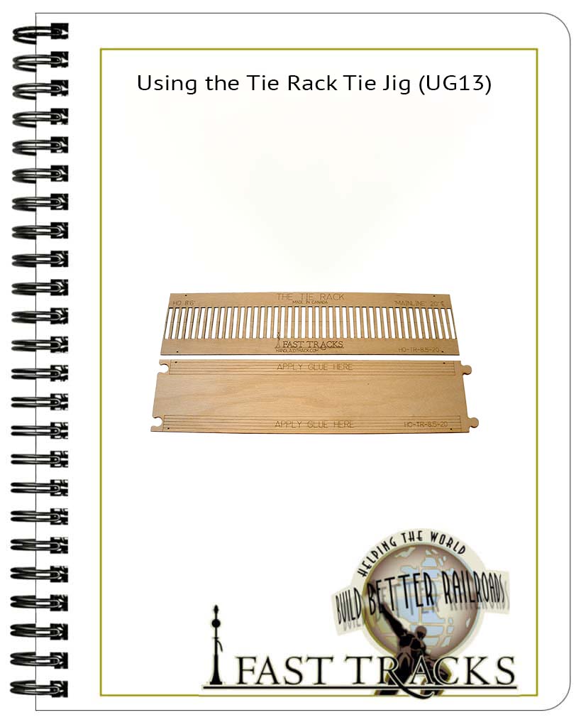
Assembling and Using the TieRack Tie Jig
Instructions on how to assemble and use your TieRack tie jig.
Download Now
Soldering Trackwork - Application Note
The techniques for creating great looking and reliable solder joints aren’t hard to master. With a bit of practice, anyone can do it. We have shown thousands of modelers how to get good results with the techniques and tools described in this document.
Download Now
Zen & the Art of spiking
After shoving in tens of thousands of spikes over the years, a routine has evolved that is giving me good results. This document reveals my secrets.